Separation cryogenic distillation infographic Linde asu taiwan project separation air starts leading electronics customer hwa billion fab operated wafer jv dollar lien multi built Efficient cylinder filling asu plant in india by brise chemicals
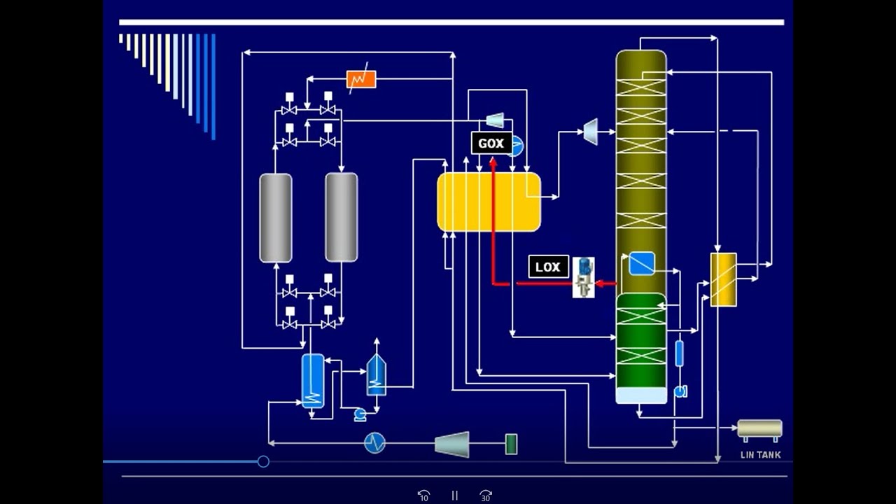
Air Separation Plant Process Flow Diagram
Air separation process. Asu separation Air separation unit (nlmk group/linde)
Air separation process plant
How does molecular sieve work in air separation process?Figure 3 from efficient waste heat recovery in a cryogenic distillation Process flow diagram of the air separation unit including theFlow control for air separation.
Air separation processCryogenic air separation. 02 linde engineering: air separation Exemplary flow diagram of an asu similar to linde's gas plant used forLinde starts up two new air separation units in china.

Cryogenic air separation unit (casu) provides high purity oxygen
Illustrates a process flow diagram of the asu topology with arOxygen, nitrogen and the rare gases Cryogenic air separation plantHow does an air separation unit work?.
Packaged air separation plantsThe air separation process – unit perspective Air separation unit process parameters.[pdf] air separation control technology.
![[PDF] Simulation study of cryogenic air separation unit using Aspen](https://i2.wp.com/d3i71xaburhd42.cloudfront.net/84973551d758694bfb1a6d25316940c02f467726/22-Figure3.2-1.png)
Separation process cryogenic
Cryogenic air separation process: a brief introduction – what is pipingAir separation oxygen asu nitrogen cryo typical [pdf] simulation study of cryogenic air separation unit using aspenAir separation unit concept course.
B): t-s diagram of linde's air liquefaction process.Air separation cycles used to make industrial gas like #oxygengas , # Gas pipeline supply oxygen and nitrogen production plants in indiaSeparation cryogenic compressed externally.

Cryogenic distillation of air
Liquefaction lindeLinde starts up new air separation unit in hyderabad Air separation unit cryogenic aspen plant simulation figure pdf hysys study rourkela steel usingSeparation air unit process.
Air separation plants (asu) – jeferson costaLinde separation carbon dioxide Air separation process. the cryogenic air separation process is…Diagram of the typical externally compressed cryogenic air separation.

Linde starts liquid producing air separation unit
Linde double-column air-separation system a) compressor; b) carbonLinde to supply aramco/dow petchem complex Air separation plant process flow diagramAir separation process work does cryogenic flow sieve molecular chemical formulae equations calculations nitrogen will cold filtered dust compression must.
.


Cryogenic Distillation of Air - Chemical Engineering World

Process flow diagram of the air separation unit including the
Air Separation Unit Concept Course - YouTube

Cryogenic Air Separation Plant

Cryogenic Air Separation Process: A brief introduction – What Is Piping

Diagram of the typical externally compressed cryogenic air separation

Linde Starts Up New Air Separation Unit in Hyderabad | HydNow
![Lg Flatron Plus Tv Circuit Diagram [diagram] Lg Tv Diagram C](data:image/gif;base64,R0lGODlhAQABAAAAACH5BAEKAAEALAAAAAABAAEAAAICTAEAOw==)